Link Design & Fabrication
Group Project
Fall 2014
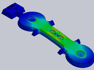
Item 7a: Stress analysis of the link that we designed. The two large holes on the extremities are for the jaws of the tensile testing machine.
As part of MEEN 361 laboratory course (Materials & Manufacturing Selection in Design), we designed, fabricated and tested a link under tensile stress.
The Task
The assignment was to design and cast an aluminum link to be placed in tension. The design should ideally have low weight and high strength (high strength to weight ratio).
The Design
The design we came up with was shaped like a 'dog-bone', as you can see from Item 7a. There are two other key features that we incorporated to improve the strength.
First, we put in 'Stress Relieve Grooves' (the 4 little lateral protrusions). These serve to relax the stress concentration that would have arose due to the reduction in cross section area from the circular regions to the rectangular region.
We also discovered, after a brief literature survey, that drilling precisely calculated holes also relieve stress (very counter-intuitive, isn't it?!). Hence the three small holes in the center. Impressively, the stress analysis showed that the point of maximum stress was no longer the center of the link but at the newly made holes, and that the maximum stress value (not shown) across the link had reduced significantly.

Item 7b: Dimensional drawing of the tensile link. (Since I designed this in the USA, all dimensions are in Inches)
Fabrication and Testing
First, the design on SolidWorks was 3D printed. This plastic print was then used to make a sand casting mold. Liquid Aluminum was poured in and an aluminum cast was obtained. We then drilled the required holes through and also machined off a layer of material on all sides, to remove any surface tensions created due to the casting process. At this point, we should've heat treated the link to improve its strength, but due to time constraints, we couldn't to do that.
Finally, we hooked up our brand new link to a tensile testing machine and loaded it to failure. Guess where it failed? Exactly where we predicted it would! (At the 0.29" dia. hole). Oh, and we were the only team in the class (of about 20 groups) whose prediction of the failure mode and location in the design matched that of actual failure during testing.